My 320x240 graphical LCD
I did it again...
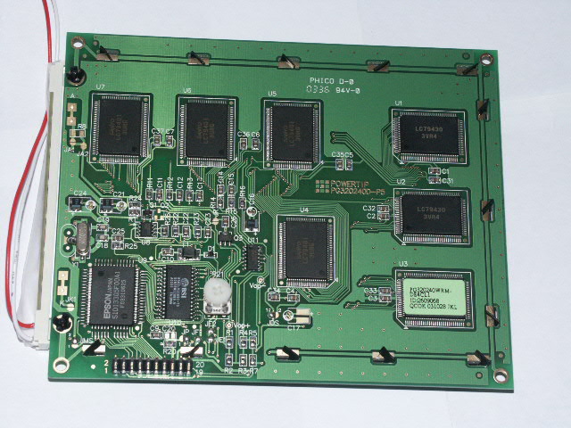
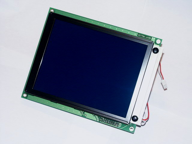
It's a Powertip PG - 320240 - D parallel drived, white on blue, graphical 320x240 pixels LCD, with a SED1335 controller, and white LED backlighted.
I pre-ordered it online from ModwareHouse, just after I finished my 240x128 LCD, for 125 Euro (about 140US$-220AUD$) without shipping and handling costs. The normal price will be 159 Euro.
(The datasheet is available at http://www.powertipusa.com/pdf/pg320240d.pdf)
After 3.5 months it finally arrived...
A few pictures:
The backlight is made of eight parallel white Leds and is specified for 160mA
at a forward voltage of 3.5V
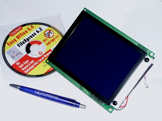
In comparison to the size of a CD and a ball pen (with my company's logo)
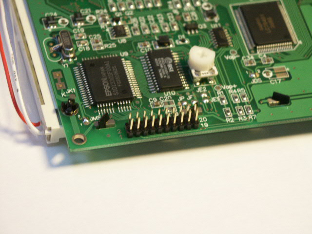
I added a 20 pin double row connector for easy connection of the LCD:
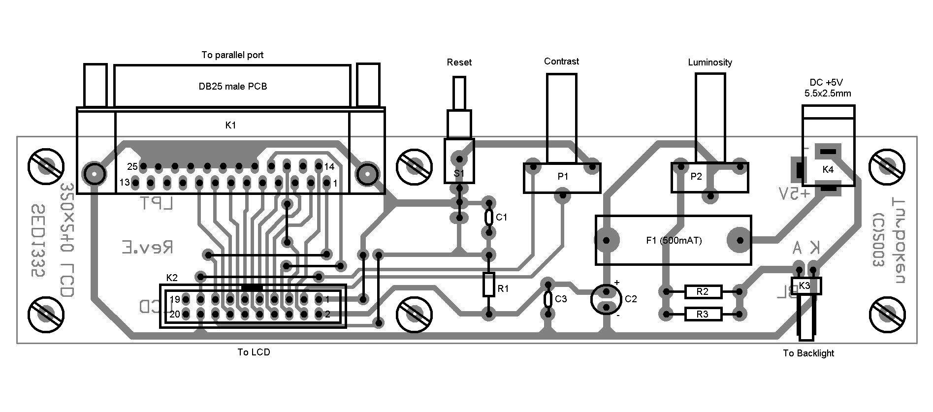
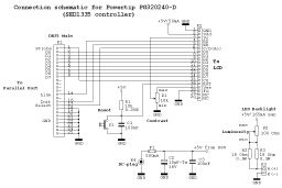
The connection schematic in Acrobat PDF format:
Components list:
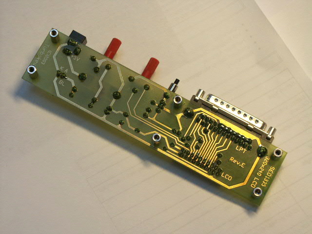
To connect the LCD to the parallel port I wanted something clean and solderless (except for the PCB ofcourse), as well as for the contrast and luminosity settings, the reset switch and the +5V connection. So again I developped a little PCB:
Remark: The PDF file is not very sharp, if interested I can upload the original Circad'98 .pcb file.
 |
 |
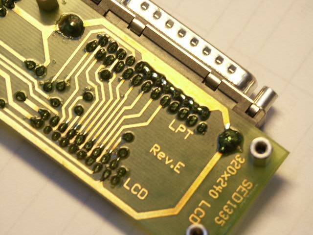 |
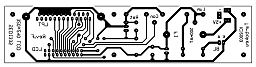
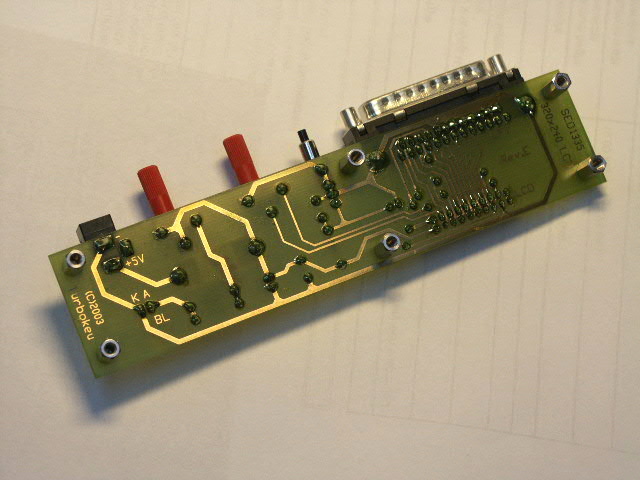
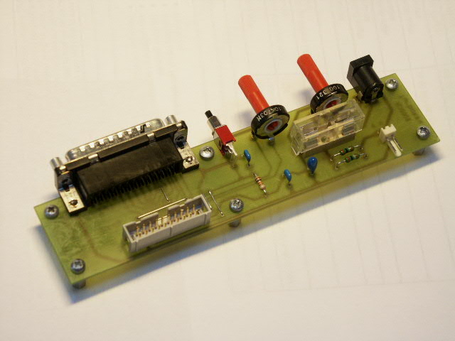
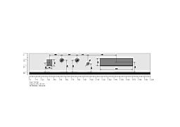
Views (from a prototype) of the PCB copper layout:
 |
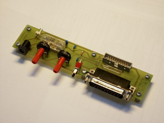 |
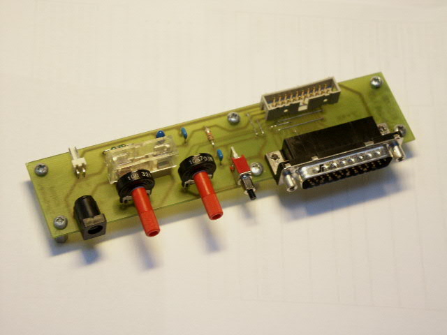
From left to right: DC +5V connector, luminosity
and contrast, reset switch, DB25 connector to parallel port. Actually power
supply is done via an external ZIP100 PSU (exactly +5V), but afterwards I want
to connect it to the Enermax +5V rail in my PC-70 through a USB cable.
Therefore I decided to include a 500mA slow blow fuse & fuseholder onto the
PCB.
 |
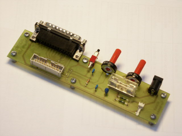 |
For the parallel port connection I used a DB25 male PCB connector, so I was able to use a standard modem extension cable (DB25 female to DB25 male). The LCD will be connected through a 20 wire flatcable with two IDC 20-pin male connectors.
Remark: After finishing the
PCB's and receiving the LCD, I noticed that a little contrast trimpotentiometer
is already mounted on the back of the PG320240. Since I provided a
contrast potentiometer on the PCB too, both interfere with each other:
The onboard trimpot acts as a raw contrast tuning, the potmeter on the PCB acts
as a fine tuning within the range of the onboard trimpot.
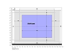
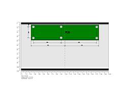
The LCD module and PCB will be mounted on a plexiglass standard (see also My 240x128 graphical LCD). The standard is ready except for all the mounting holes. The following diagrams show the drilling measures.
 |
 |
 |
Drilling diagrams of the front, base and back panels (in PDF format)
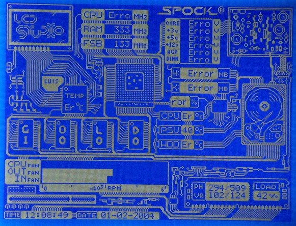
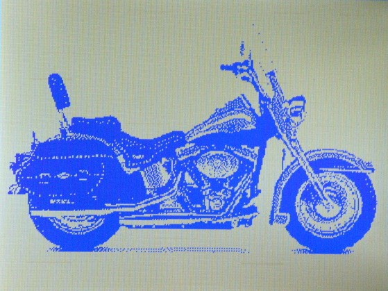
Since the actual version (2.02) of PowerLCD does not support SED1335 controllers I will use the freeware LcdStudio 1.5 software. It's actually the only software (together with the LiquidMP3 Winamp plugin) that supports SED1335 controllers and LCD's with a resolution of 320x240 pixels and above.
Update: It seems that LcdHype should work also with SED1335 controllers, but at this time I couldn't make it to happen...
Some pictures with LcdStudio 1.5 :
 |
 |
 |
 |
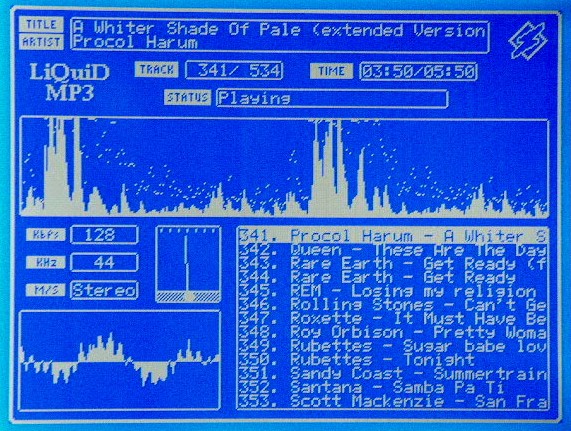
With LiquidMP3 :
Pictures of the finished LCD will follow soon...